OSHA Section 1926.756: Quick Reference for Beams and Columns
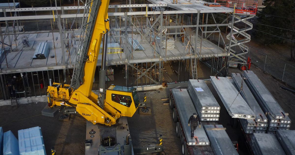
Erecting structural steel frames introduces serious stability risks if connections are unhooked prematurely or columns lack the proper dimensional clearances for perimeter safety cables. For estimators, project managers, and trade contractors coordinating around structural steel installation, understanding eCFR Section 1926.756 is critical for evaluating hook time, equipment schedules, and fabrication requirements.
Hoisting Releases and Primary Solid Web Connections
The standard establishes firm baseline rules for when a crane line may disconnect from a newly positioned structural steel piece. When crews perform the final placing of solid web structural members, the hoisting line cannot release the load until the members are secured at each connection with at least two bolts. These fasteners must match the exact size and strength indicated on the erection drawings. In addition, workers must pull them up wrench-tight, or establish an equivalent tightness specified by the project structural engineer of record.
Estimators pricing steel installation packages must factor this requirement directly into crane duration calculations. A hoist line cannot simply set a beam and swing away to retrieve the next member; it must maintain position while ironworkers align the holes and wrench-tighten at least two bolts per connection point.
Diagonal Bracing and Cantilevered Member Stability
Section 1926.756 allows a specific exception for solid web structural members utilized as diagonal bracing. For these bracing members, crews must secure each connection with at least one bolt drawn up wrench-tight or the equivalent established by the project structural engineer of record. This single-bolt allowance reflects the different loading condition of diagonal braces compared to load-bearing primary framing beams.
Conversely, cantilevered structural steel members require heightened oversight. Under OSHA Section 1926.756, a designated competent person must evaluate whether more than two bolts are required to guarantee stability. If that competent person decides additional bolts are needed, the crew must install them before hoisting lines release the load. When bidding frames with long overhangs, estimators must anticipate potential delays for competent person reviews and additional bolt installation.
Double Connections at Column and Beam Webs
Making double connections where two framing members share holes across a column web or beam web creates a hazard where backing out bolts could leave the initial beam unsupported. The standard mandates specific safeguards:
- When two structural members attach to opposite sides of a column web, or a beam web situated over a column, sharing common connection holes, at least one bolt with a wrench-tight nut must stay attached to the first member.
- The only alternative permitted is if the member includes a shop-attached or field-attached seat, or an equivalent connection device, to secure the first member and prevent column displacement (appendix H provides examples).
- When seats or equivalent devices are used, they must be engineered to carry the load throughout the entire double connection process.
- Crews must adequately bolt or weld the seat to both the first member and the supporting member before removing shared nuts to complete the double connection.
Failing to verify whether shop seats exist can add significant field welding or complex staging to your erection sequence. Review these interfaces during pre-bid drawing reviews, or address support device requirements through your Estimating General Conditions: The Job Costs That Aren't in Your Takeoff evaluation.
Column Splice Strength and Perimeter Column Rules
Splices between column sections must satisfy strict eccentric load resistances. Under paragraph (d), every column splice must be engineered to withstand a minimum eccentric gravity load of 300 pounds (136.2 kg) applied 18 inches (.46 m) away from the column's extreme outer face in each direction at the top of the column shaft. This engineering rule prevents premature joint failures prior to completing final structural tie-ins.
Perimeter columns also carry strict requirements designed to facilitate subsequent fall protection installations under Section 1926.760(a)(2). Specifically, perimeter columns cannot be erected unless they meet two criteria:
- They must extend a minimum of 48 inches (1.2 m) above the finished floor level to allow installation of perimeter safety cables before the next tier is erected, unless constructibility prevents it under appendix F.
- They must feature holes or attached devices located at 42-45 inches (107-114 cm) above the finished floor, along with another set at the midpoint between the finished floor and the top cable, to support the perimeter safety cables required by Bidding OSHA 1926.760 Steel Erection Fall Protection Rules, unless constructibility dictates otherwise.
Estimating Checklist for Connection Compliance
To avoid scope gaps or unexpected field downtime during steel frame erection, bidders should cross-check connection requirements across drawings and project specifications:
- Confirm whether erection drawings indicate beam-to-column connections that share holes, and verify if seats are shop-installed by the fabricator.
- Account for crane standby minutes while ironworkers install at least two bolts wrench-tight on solid web members before unhooking.
- Allocate time for diagonal bracing installations requiring at least one bolt wrench-tight per connection.
- Confirm perimeter columns include pre-punched holes at 42-45 inches (107-114 cm) and the intermediate midpoint to allow immediate safety cable stringing.
- Verify that perimeter column lengths provide the required minimum of 48 inches (1.2 m) above finished slab elevations.
Sources
Details in this explainer are drawn directly from the federal safety regulations codified in eCFR Section 1926.756: Beams and columns.
Published October 28, 2026. No affiliate links on this page. Facts come from the sources linked above; check them for updates.