Spray Booth Design and Construction Rules (29 CFR 1926.66): What Painting and Coating Subs Must Provide on Site
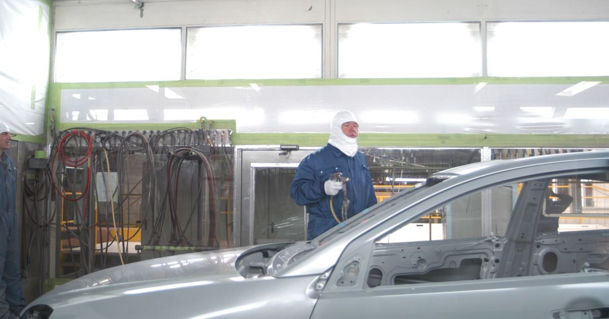
When commercial interior packages require extensive off-line finishing, painting and coating trade contractors often install temporary or permanent booths inside jobsite boundaries. Under federal safety standards, constructing or operating a booth triggers strict mechanical, structural, and electrical mandates. The following scenario walks through how a hypothetical coating subcontractor reviews and coordinates an on-site dry spray booth installation under the explicit provisions of 29 CFR 1926.66.
Walk-Through Step: Enclosure Shell and Boundary Clearances
In our hypothetical walkthrough, the coating crew must erect a power-ventilated dry spray booth inside an open warehouse bay undergoing alteration. The first task is establishing the booth physical structure. Under OSHA rules, the booth must be substantially constructed of steel that is securely and rigidly supported, or made of concrete or masonry. Aluminum or other substantial noncombustible material remains an allowable alternative solely for intermittent or low volume spraying. The interior surfaces must be smooth and continuous without edges, arranged to sweep air currents toward the exhaust outlet while preventing the pocketing of residues so workers can clean or wash the walls safely.
Floor conditions require immediate preparation. If the existing floor surface of the booth or the operator working area is combustible, the crew must cover it with noncombustible material that facilitates safe residue removal. Around the structure perimeter, the team marks out required buffer zones. The booth must be separated from other operations by not less than 3 feet (0.912 m), or by a greater distance, or by an effective partition. Furthermore, a clear space of not less than 3 feet (0.912 m) on all sides must remain completely free from stored materials or combustible construction so maintenance crews retain full cleaning access.
Because the hypothetical booth entrance has a frontal area larger than 9 square feet, the crew secures a metal deflector or curtain not less than 2 1/2 inches (5.35 cm) deep installed directly at the upper outer edge over the opening. If parts enter via conveyors, those conveyor openings must be kept as small as practical.
Walk-Through Step: Air Velocity and Dry Filter Provisions
With the physical shell outlined, the subcontractor configures the dry type overspray collection system. The project team selects dry overspray filters to capture particulates before air enters the ductwork. If distribution or baffle plates are installed to balance airflow or catch overspray, they must consist of noncombustible material, remain readily removable or accessible on both sides for cleaning, and never sit inside the exhaust ducts themselves.
For standard spraying operations, the ventilation equipment must maintain an average air velocity over the open face of the booth (or the booth cross section during operations) of not less than 100 linear feet per minute. If the crew were instead conducting electrostatic spraying operations, the standard permits an open face velocity of not less than 60 linear feet per minute, or more depending on coating volume and flammability. To prove compliant airflow in real time, the installer must provide visible gauges, an audible alarm, or pressure-activated devices. In addition, the space within the booth on both the downstream and upstream sides of the filters must be protected with approved automatic sprinklers.
The subcontractor also institutes daily housekeeping routines for overspray media. Clean replacement filters must be noncombustible or rated with combustibility not in excess of class 2 filters as listed by Underwriters' Laboratories, Inc. Discarded filter pads or rolls cannot pile up near work areas; crews must immediately remove them to a safe, well-detached location or submerge them in a water-filled metal container, followed by complete disposal at the close of the day's operation.
Walk-Through Step: Managing Electrical Zones and Ignition Hazards
Next, the walkthrough focuses on hazardous location boundaries. The standard establishes clear zones to prevent fire and vapor ignition:
- No Open Flames or Sparks: No open flame or spark-producing equipment is permitted inside any spraying area nor within 20 feet (6.08 m) unless fully isolated by a physical partition.
- Spraying Area Wiring: Electrical equipment inside the booth cannot accumulate combustible residues unless specifically approved for both ignitable residues and explosive vapors. Permitted wiring must run inside rigid conduit or boxes and fittings free of taps, splices, or terminal connections. Approved electrical apparatus must meet explosion-proof ratings for Class I, group D locations and satisfy subpart S requirements for Class I, Division 1 hazardous locations.
- Outer Perimeter Wiring: Electrical wiring, motors, and lamps outside the spraying area but within 20 feet (6.08 m)—and not isolated by partitions—must meet Class I, Division 2 standards and produce no sparks during normal operation. Electric lamps in this zone must be totally enclosed to prevent hot particles from dropping.
- Lighting Panels and Portables: Illumination through transparent panels requires fixed, isolated lighting units made of protected, noncombustible material that keeps surface residues below dangerous temperatures. Portable electric lamps are prohibited during spraying, and any portable lamp used during cleaning or maintenance must carry Class I approval.
- System Grounding: All metal parts of the spray booth, exhaust ducts, and liquid or aerated powder piping must be electrically grounded in an effective, permanent manner.
Accounting for these specialized containment and electrical setups during project mobilization is a key part of pricing jobsite general conditions.
Walk-Through Step: Mechanical Exhaust and Exterior Discharge
The final phase of the walkthrough addresses ductwork fabrication and discharge termination under OSHA 29 CFR 1926.66 and NFPA No. 91-1961. The booth must feature an independent exhaust duct system discharging outdoors. Electric motors driving exhaust fans cannot sit inside booths or ducts, and belts passing through must be thoroughly enclosed. The fan rotating element must be nonsparking or nonferrous, or run within a lined casing, maintaining ample internal clearances to avoid friction fire.
Exhaust ducts must be built of steel, substantially supported, and run with a standard clearance of not less than 18 inches (45.72 cm) from unprotected combustible material. If that buffer is tight, clearances may be reduced using specific noncombustible insulation assemblies: to 12 inches (30.48 cm) with 28-gage sheet metal on 1/4-inch asbestos mill board; to 9 inches (22.86 cm) with 28-gage sheet metal on 1/8-inch asbestos mill board spaced out 1 inch (2.54 cm) on noncombustible spacers; to 3 inches (7.62 cm) with 22-gage sheet metal on 1-inch rockwool batts reinforced with wire mesh; or to 6 inches (15.24 cm) where ducts are protected with an approved automatic sprinkler system.
Outside the facility, the non-waterwash exhaust duct terminal must terminate not less than 6 feet from any combustible exterior wall or roof. Additionally, the duct cannot discharge toward combustible construction or unprotected openings in noncombustible exterior walls within 25 feet (7.6 m). Clarifying who furnishes roof penetrations and power feeds avoids misunderstandings on site, making clear trade language essential when drafting bid exclusions and clarifications.
Sources
Published October 31, 2026. No affiliate links on this page. Facts come from the sources linked above; check them for updates.